3D architectured graphene nanolattice
Carbon nanolattices: optimized lattices with ultra strong constituents
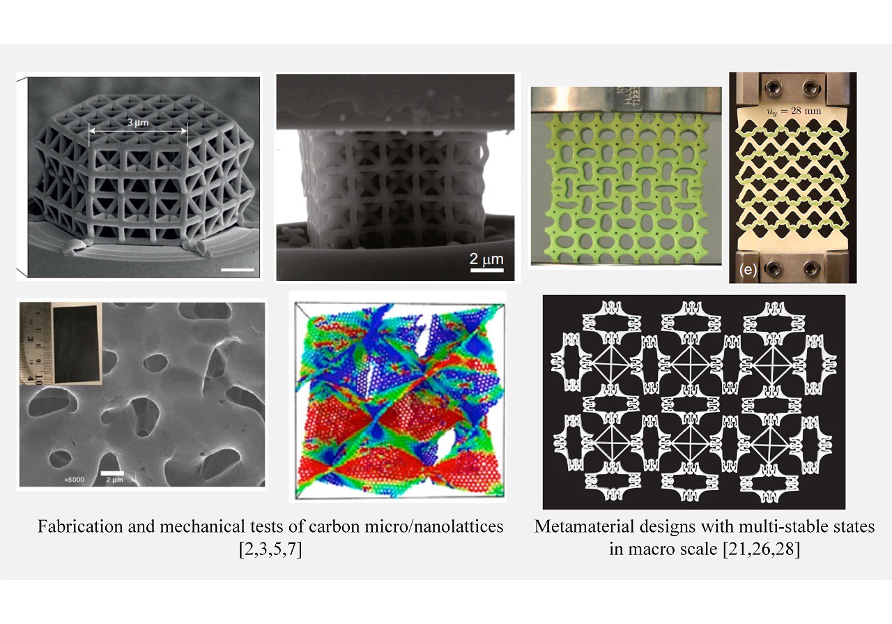
Carbon micro/nano lattices are a unique family of architected metamaterials constructed from micro/nano-scale carbon constituents [1]. During the past few years, they have demonstrated exciting potentials in reaching theoretical limits of mechanical performances as well as integrating properties which are often mutually exclusive through experimental studies and numerical simulations [2-8]. The combination of small-scale carbon constituents and unlimited architecture designs of lattice opens a broad exploration space for better material properties in carbon nanolattices.
For 3D graphene, ductility matters
Besides pursuing high specific strength, ductility is also particularly important to carbon nanolattices for robust performances [7].
- At the material level, the carbon constituents, most made of graphene, are strong but intrinsically brittle [14]. To make use of the ultrahigh strength of graphene, it is also important to enhance the toughness and ductility.
- At the structure level, buckling is an important mechanism to dissipate energy in nanolattice materials under compression [16-18]. However, permanent and continuous damage often accompanies buckling events. Under tensile loading, buckling can have much limited effect on energy dissipation [4, 5]. Given the great potentials of carbon nanomaterials, it is important to enrich the design library of carbon nanolattices with examples of novel energy dissipation mechanisms in order to overcome this challenge.
Snap-through instability: marco and micro scales
Like buckling, snap-through instability has been a long-time research topic [22-29]. Recent studies unveil some unique advantages of this instability.
- On one hand, at macro-scale, sequential snap-through instabilities can be triggered under compressive and tensile loading conditions [25, 28] with little irriversibkle damage [28]. Metamaterials with snap-through instability often exhibit multiple mechanically stable states, which open doors to the design of shape-reconfigurable materials (SRMs) [25].
- On the other hand, at small scales, basic conceptual units with mechanically bi-stable states and snap-through instability [30-33] have been adopted to explain deformation behaviors of phase transforming materials, including structure proteins with compactly folded or unfolded domains [34, 35] and shape memory alloys undergoing martensitic phase transformation [36].
Such universal structure-to-property relationship indicates great potential in engineering complex overall deformation behavior via bi-stable units and snap-through instabilities.
Can we use snap-through to toughen graphene nanolattices?
Through mechanism-inspired topological design,we present a novel design of 3D graphene nanolattice that can have multiple stable states with snap-through instability and demonstrate pseudo plastic deformation and hysteresis to effectively dissipate deformation energy and tolerate crack-like flaws.
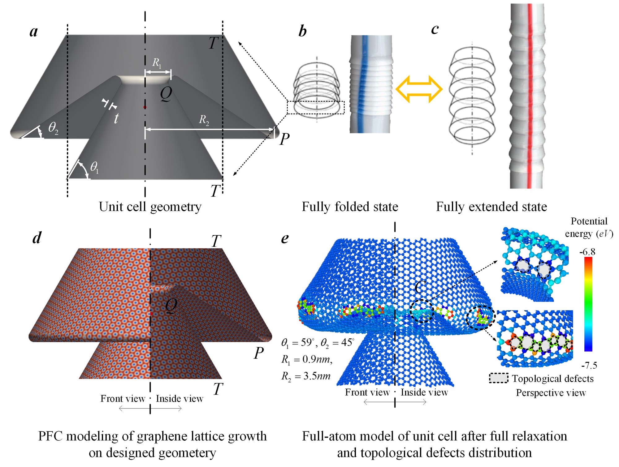
At macroscale, the flexible straw [43, 44] can change length by transforming between the folded state and the extended state (Fig. 2b and 2c). The states are mechanically stable [45]. Here, we constructed a full-atom model of graphene counterpart to such a unit cell by taking advantage of the methodology of topological design [46-48], which includes
- phase field crystal modeling [49-51] of growing 2D crystal on the designed geometry of the conical frustra (Fig. 2d),
- thermal relaxation of the obtained crystal structure via MD.
Unit cells with straw-like topology are constructed with graphene (which may be the thinnest straw).
These graphene straw unit cells can distingush from their conterpart at large scale due to
- the presence of topological defects [46, 53], such as disclinations and dislocations, at the connections of the two frustra to accommodating and stabilizing the curvature transition (Fig. 2e),
- the residual stess coming with the topolgoical defects,
- the Van der Waals (VdW) interactions [54] between graphene surfaces.
Can this graphene straw snap?
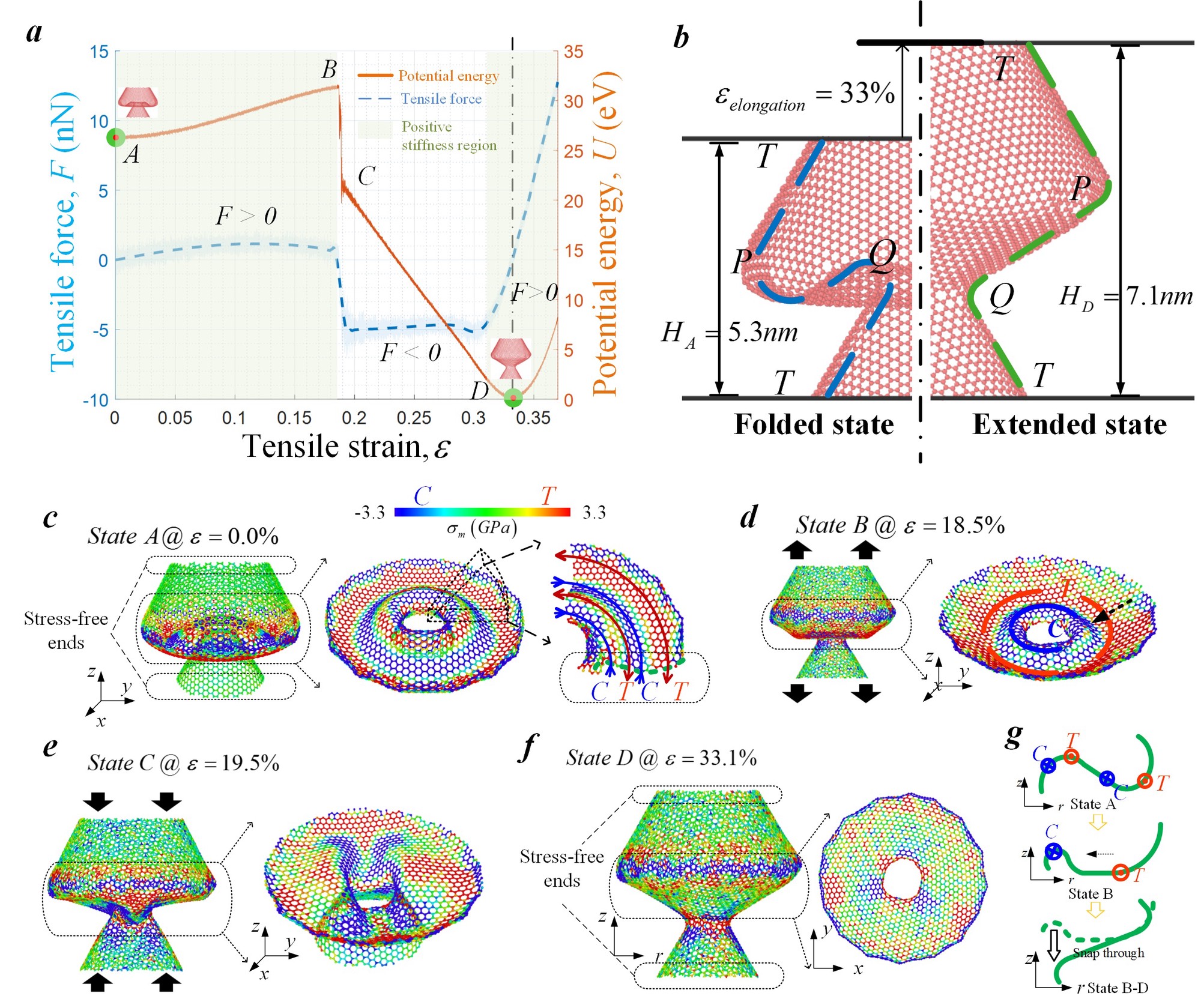
By pulling the unit cell via MD, we observe the snap-through between the folded state and the extended state (Fig. 3b) and the force-strain and potential energy-strain curves (Fig. 3a). Indeed, there exists two mechanically stable states and the sample snaps between them.
As shown Fig. 3c and 3d, the snap-through event mainly takes place at the inner frustum (P-Q in Fig. 3b) with the outer frustum (Q-T-P in Fig. 2 b) serving as a constraint to its deformation.
- At the folded state, the inner frustum is already self-stressed under no external loading (Fig. 3c).
- At the critical moment, the axial-symmetry of the deformation is broken (Fig. 3e) and the inner frustrum flips out (Fig. 3f). Compared to the folded state (Fig. 3c), the residual stress in the inner frustrum is reduced in the extended state (Fig. 3c and 3f).
In the following section, we combine the unit cell with different lattice designs to construct 1D and 3D graphene nanolattices and study their collective deformation behaviors, aiming at engineering effective energy dissipation by leveraging the effect of the snap-through instability.
1D lattice: straw-like carbon nanotubes (SCNTs)
Straightforwardly, by repeating the unit cell along the axial direction, we obtain the 1D lattice of a straw-like CNT (SCNT). The SCNT sample can have multiple mechanically stable states with different lengths. The force-strain curve shows snap-through events with energy dissipation (Fig. 4a and 4b).
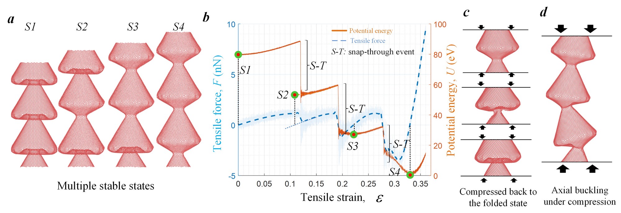
However, it can be hard to transform the extended configuration back to the folded one due to global axial buckling of SCNT under compression.
- With small axial length, like one unit cell, SCNT can be compressed back (Fig. 4c)
- As the axial length increases, SCNT buckles along axial direction before snap-through can happen (Fig. 4d). This asymmetry in tension and compression limits the reconfigurability of 1D SCNT in cyclic loading. Next, we construct a 3D lattice to overcome this limitation.
3D graphene nanolattice: connected SCNT bundles
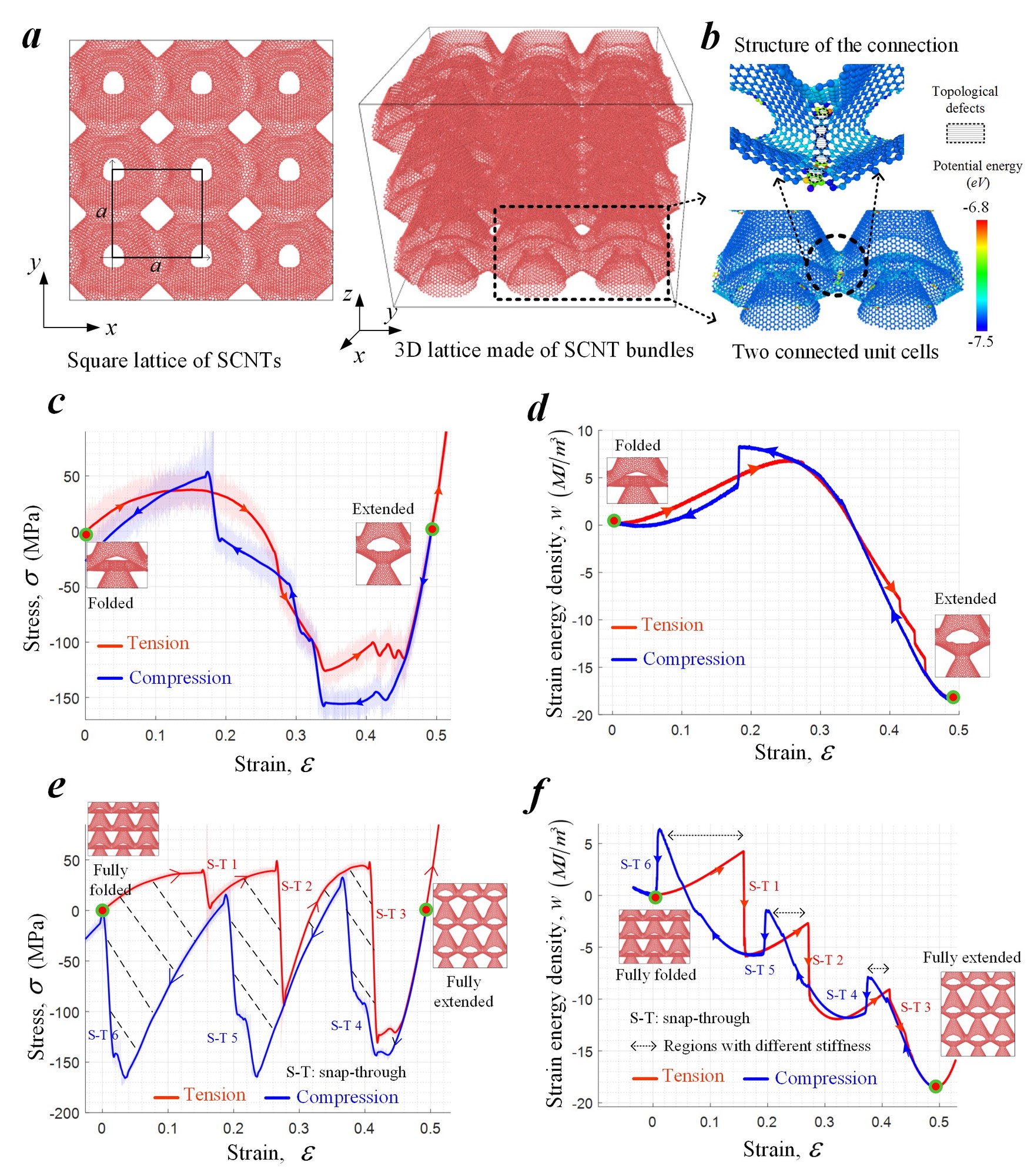
3D lattices are construted as the following (Fig. 5a and 5b).
- Parallel 1D SCNTs are assembled into a bundle-like architecture according to a square lattice.
- Neighboring SCNTs are interconnected through covalent bonding
MD simulations demonstrates that these 3D graphene nanolattices can snap forward and backward between the fully folded and extended states under cyclic loading without suffering global buckling or irreversible damage (See Movie M3 and M4), which makes them elastically reconfigurable.
Tension and compression paths of 3D graphene nanolattice
Deformation modes: Single unit cell vs collective lattice
It should be noted that the number of unit cells along the axial direction can affect the deformation behavior of the 3D graphene nanolattices. In the case of one single unit cell under cyclic loading, the mechanical responses along tension and compression paths show very limited differences which means very limited energy dissipation (Fig. 5c and 5d). However, in the case of multiple unit cells, saw-teeth like stress-strain curves are observed (Fig. 5e and 5f) and the stress-strain history takes different paths under tension and compression. Correspondingly, a hysteresis loop appears and energy associated with the loop is dissipated after the cycle. Intuitively, this hysteresis behavior can be related to the snap-through instability. To systematically explain the relationship between the hysteresis behavior, snap-through instability and multi-stable configurations, a theoretical model is developed in the next section.
Theoretical model: 1D bi-stable element chain
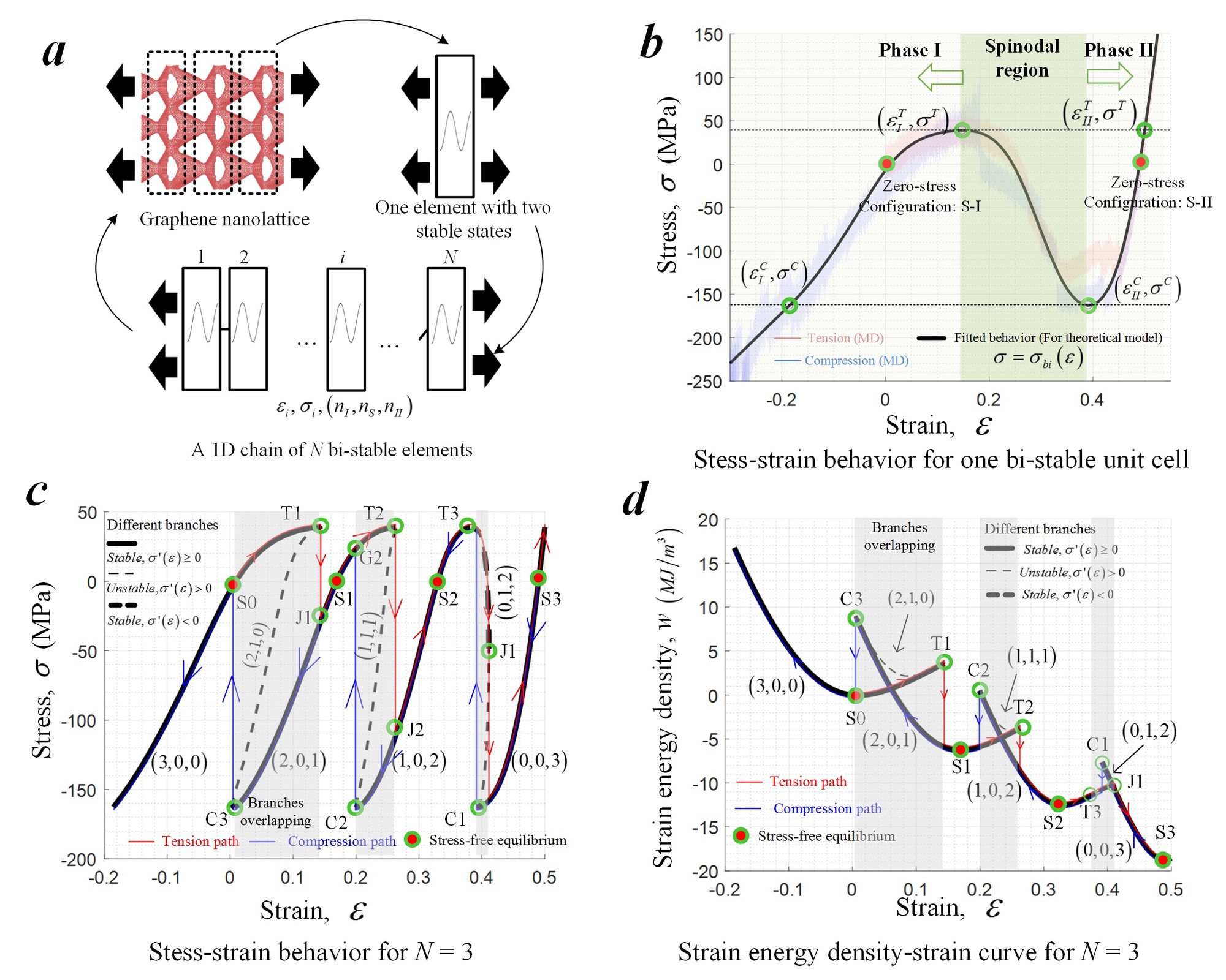
We adopted a theoretical model of 1D chain of bi-stable elements to study the nanolattices (Fig. 6a) phenomenologically.
- The unit cell is characterized by the stress-strain curve with a spinodal region and two stress-free equilibrium configurations with different lengths and stiffnesses, Phase I and II ( Fig. 6b)
- The unit cells are identical and connected one after another along the axial direction.
- We define the state of the system using the numbers of elements in the Phase I, II and spinodal region respectively. Different states correspond to different load-free equilibrium configurations.
Assume the deformation process is quasi-static and over-damped. By force balance and stable equlibrium condition, we can find for a given displacement-controlled loading path (Fig. 6c and 6d),
- multiple deforamtion branches with different system states exits;
- These branches often discontinous;
- These branches have overlapping in the strain interval.
By applying the condition of the continouity of loading strain, we can find the realized deformation path. The theortical model explains the observation of MD simulations. Specificly,
- the discontinuity of stable deformation branches results in the saw-teeth like stress-strain curves;
- the overlapping of stable deformation branches leads to the hysteresis loop in cyclic loading.
The theoretical prediction and the MD simulations show a good agreement (Fig. 7a and 7b).
What happens when the lattice have a large number of unit cells?
Comparing the MD results, we noted that as the number of unit cell along the axial direction increases,
- the amplitude of stress oscillations along tension/compression paths decreases
- the area of hysteresis loop increases.
Based on this observation, it becomes interesting to predict
- the asymptotic behavior of nanolattice samples with large numbers of unit cells
- the upper bound of energy dissipation for this nanolattice design
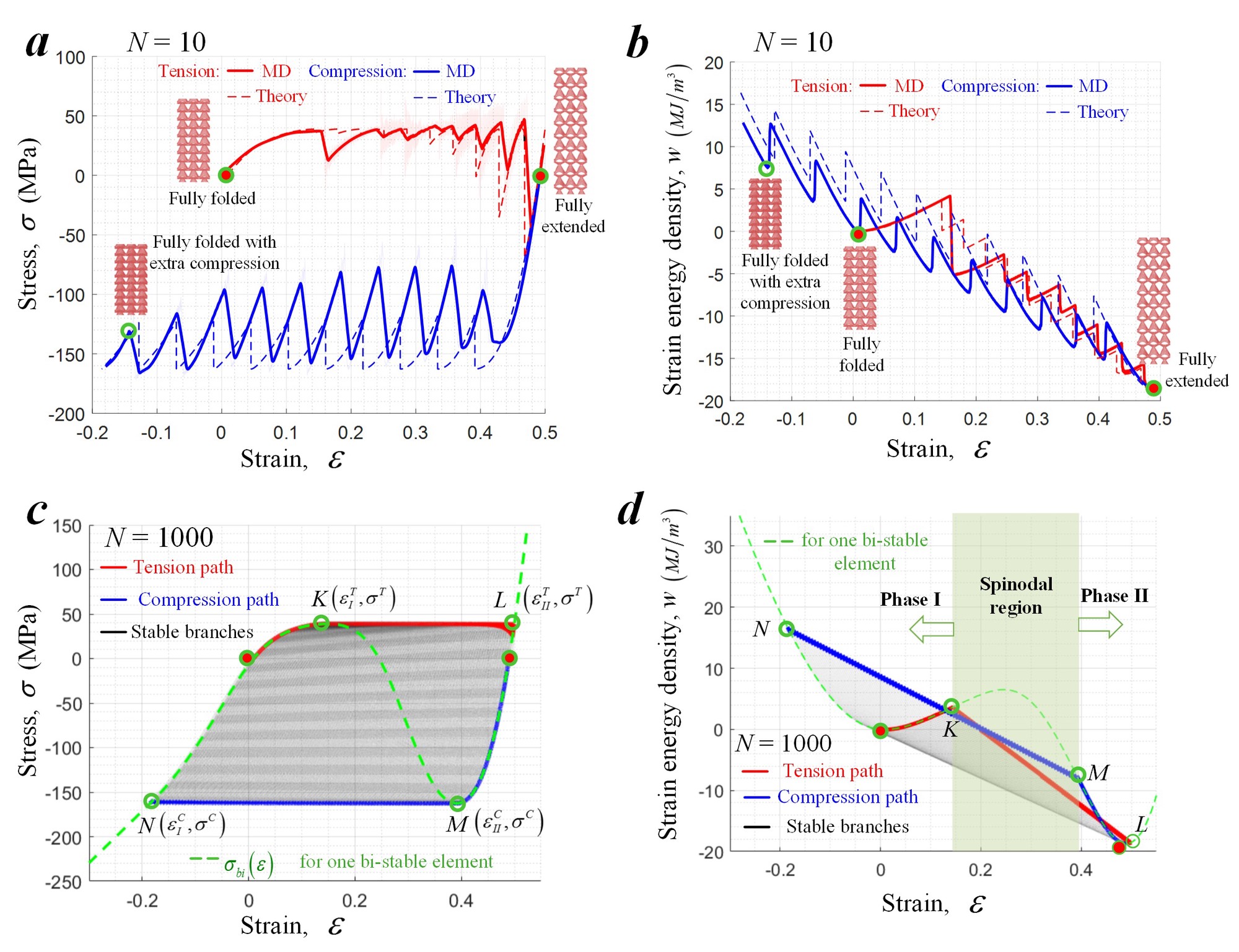
By keeping increasing unit cell number in the theoretical model, we observed the deformation behavior converges to (Fig. 7c and 7d)
- a pseudo plastic behavior: yield and flow happens without irriversible damage,
- a finite hysteresis loop dissipating strain energy.
With these toughening mechanisms, the energy dissipation per unit mass of graphene nanolattice for a full loop between the fully folded and extended states can approach 233 kJ/kg (One order higher than the energy absorbed by carbon steel at failure, 16 kJ/kg ).
Flaw tolerance: Loading with an edge crack
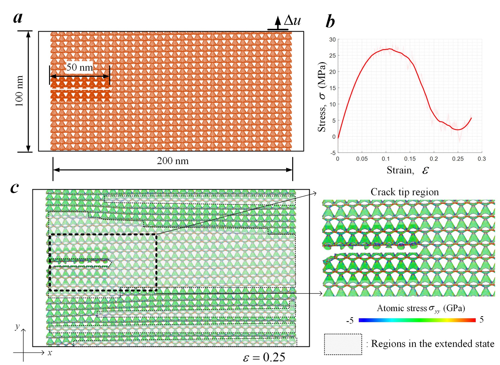
At last, we demonstrated the effect of the energy dissipation mechanisms enabled in this novel 3D graphene nanolattice on resisting crack propagation.
In the graphene nanolattice, it is observed that unit cells near the crack tip transform from the folded state into the extended one first. Correspondingly, the stress near the crack tip region is mostly released and the crack tip is trapped (Fig. 8c). As the transformation region expands through the lattice, the overall stress level also decreases (Fig. 8b) due to the reconfiguration of the nanolattice.
Therefore, the graphene nanolattice with snap-through instability can tolerate crack-like flaw and behave in a ductile manner within the pseudo plastic deformation region.
- Ni B, Gao H. Engineer Energy Dissipation in 3D Graphene Nanolattice Via Reversible Snap-Through Instability. Journal of Applied Mechanics. 2020 Mar 1;87(3).
